AirSim Settings
Where are Settings Stored?
Windows: Documents\AirSim
Linux: ~/Documents/AirSim
The file is in usual json format. On first startup AirSim would create settings.json file with no settings. To avoid problems, always use ASCII format to save json file.
How to Chose Between Car and Multirotor?
The default is to use multirotor. To use car simple set "SimMode": "Car" like this:
To choose multirotor, set "SimMode": "Multirotor". If you want to prompt user to select vehicle type then use "SimMode": "".
Available Settings and Their Defaults
Below are complete list of settings available along with their default values. If any of the settings is missing from json file, then default value is used. Some default values are simply specified as "" which means actual value may be chosen based on the vehicle you are using. For example, ViewMode setting has default value "" which translates to "FlyWithMe" for drones and "SpringArmChase" for cars.
WARNING: Do not copy paste all of below in your settings.json. We strongly recommend adding only those settings that you don’t want default values. Only required element is "SettingsVersion".
SimMode
SimMode determines which simulation mode will be used. Below are currently supported values:
"": prompt user to select vehicle type multirotor or car"Multirotor": Use multirotor simulation"Car": Use car simulation"ComputerVision": Use only camera, no vehicle or physics
ViewMode
The ViewMode determines which camera to use as default and how camera will follow the vehicle. For multirotors, the default ViewMode is "FlyWithMe" while for cars the default ViewMode is "SpringArmChase".
FlyWithMe: Chase the vehicle from behind with 6 degrees of freedomGroundObserver: Chase the vehicle from 6’ above the ground but with full freedom in XY plane.Fpv: View the scene from front camera of vehicleManual: Don’t move camera automatically. Use arrow keys and ASWD keys for move camera manually.SpringArmChase: Chase the vehicle with camera mounted on (invisible) arm that is attached to the vehicle via spring (so it has some latency in movement).NoDisplay: This will freeze rendering for main screen however rendering for subwindows, recording and APIs remain active. This mode is useful to save resources in “headless” mode where you are only interested in getting images and don’t care about what gets rendered on main screen. This may also improve FPS for recording images.
TimeOfDay
This setting controls the position of Sun in the environment. By default Enabled is false which means Sun’s position is left at whatever was the default in the environment and it doesn’t change over the time. If Enabled is true then Sun position is computed using longitude, latitude and altitude specified in OriginGeopoint section for the date specified in StartDateTime in the string format as %Y-%m-%d %H:%M:%S, for example, 2018-02-12 15:20:00. If this string is empty then current date and time is used. If StartDateTimeDst is true then we adjust for day light savings time. The Sun’s position is then continuously updated at the interval specified in UpdateIntervalSecs. In some cases, it might be desirable to have celestial clock run faster or slower than simulation clock. This can be specified using CelestialClockSpeed, for example, value 100 means for every 1 second of simulation clock, Sun’s position is advanced by 100 seconds so Sun will move in sky much faster.
OriginGeopoint
This setting specifies the latitude, longitude and altitude of the Player Start component placed in the Unreal environment. The vehicle’s home point is computed using this transformation. Note that all coordinates exposed via APIs are using NED system in SI units which means each vehicle starts at (0, 0, 0) in NED system. Time of Day settings are computed for geographical coordinates specified in OriginGeopoint.
SubWindows
This setting determines what is shown in each of 3 subwindows which are visible when you press 0 key. The WindowsID can be 0 to 2, CameraName is any available camera on the vehicle. ImageType integer value determines what kind of image gets shown according to ImageType enum. For example, for car vehicles below shows driver view, front bumper view and rear view as scene, depth and surface normals respectively.
Recording
The recording feature allows you to record data such as position, orientation, velocity along with the captured image at specified intervals. You can start recording by pressing red Record button on lower right or the R key. The data is stored in the Documents\AirSim folder, in a time stamped subfolder for each recording session, as tab separated file.
RecordInterval: specifies minimal interval in seconds between capturing two images.RecordOnMove: specifies that do not record frame if there was vehicle’s position or orientation hasn’t changed.Cameras: this element controls which cameras are used to capture images. By default scene image from camera 0 is recorded as compressed png format. This setting is json array so you can specify multiple cameras to capture images, each with potentially different image types. When PixelsAsFloat is true, image is saved as pfm file instead of png file.
ClockSpeed
This setting allows you to set the speed of simulation clock with respect to wall clock. For example, value of 5.0 would mean simulation clock has 5 seconds elapsed when wall clock has 1 second elapsed (i.e. simulation is running faster). The value of 0.1 means that simulation clock is 10X slower than wall clock. The value of 1 means simulation is running in real time. It is important to realize that quality of simulation may decrease as the simulation clock runs faster. You might see artifacts like object moving past obstacles because collision is not detected. However slowing down simulation clock (i.e. values < 1.0) generally improves the quality of simulation.
Segmentation Settings
The InitMethod determines how object IDs are initialized at startup to generate segmentation. The value “” or “CommonObjectsRandomIDs” (default) means assign random IDs to each object at startup. This will generate segmentation view with random colors assign to each object. The value “None” means don’t initialize object IDs. This will cause segmentation view to have single solid colors. This mode is useful if you plan to set up object IDs using APIs and it can save lot of delay at startup for large environments like CityEnviron.
If
OverrideExistingis false then initialization does not alter non-zero object IDs already assigned otherwise it does.If
MeshNamingMethodis “” or “OwnerName” then we use mesh’s owner name to generate random hash as object IDs. If its “StaticMeshName” then we use static mesh’s name to generate random hash as object IDs. Note that it is not possible to tell individual instances of the same static mesh apart this way, but the names are often more intuitive.
Camera Settings
The CameraDefaults element at root level specifies defaults used for all cameras. These defaults can be overridden for individual camera in Cameras element inside Vehicles as described later.
Note on ImageType element
The ImageType element in JSON array determines which image type that settings applies to. The valid values are described in ImageType section. In addition, we also support special value ImageType: -1 to apply the settings to external camera (i.e. what you are looking at on the screen).
For example, CaptureSettings element is json array so you can add settings for multiple image types easily.
CaptureSettings
The CaptureSettings determines how different image types such as scene, depth, disparity, surface normals and segmentation views are rendered. The Width, Height and FOV settings should be self explanatory. The AutoExposureSpeed decides how fast eye adaptation works. We set to generally high value such as 100 to avoid artifacts in image capture. Similarly we set MotionBlurAmount to 0 by default to avoid artifacts in ground truth images. The ProjectionMode decides the projection used by the capture camera and can take value “perspective” (default) or “orthographic”. If projection mode is “orthographic” then OrthoWidth determines width of projected area captured in meters.
For explanation of other settings, please see this article.
NoiseSettings
The NoiseSettings allows to add noise to the specified image type with a goal of simulating camera sensor noise, interference and other artifacts. By default no noise is added, i.e., Enabled: false. If you set Enabled: true then following different types of noise and interference artifacts are enabled, each can be further tuned using setting. The noise effects are implemented as shader created as post processing material in Unreal Engine called CameraSensorNoise.
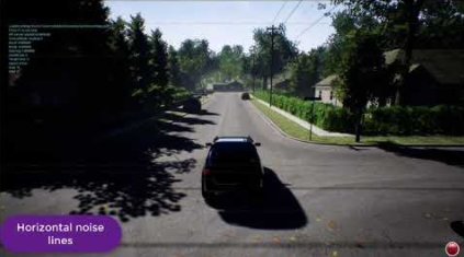
Demo of camera noise and interference simulation:
Random noise
This adds random noise blobs with following parameters.
RandContrib: This determines blend ratio of noise pixel with image pixel, 0 means no noise and 1 means only noise.RandSpeed: This determines how fast noise fluctuates, 1 means no fluctuation and higher values like 1E6 means full fluctuation.RandSize: This determines how coarse noise is, 1 means every pixel has its own noise while higher value means more than 1 pixels share same noise value.RandDensity: This determines how many pixels out of total will have noise, 1 means all pixels while higher value means lesser number of pixels (exponentially).
Horizontal bump distortion
This adds horizontal bumps / flickering / ghosting effect.
HorzWaveContrib: This determines blend ratio of noise pixel with image pixel, 0 means no noise and 1 means only noise.HorzWaveStrength: This determines overall strength of the effect.HorzWaveVertSize: This determines how many vertical pixels would be effected by the effect.HorzWaveScreenSize: This determines how much of the screen is effected by the effect.
Horizontal noise lines
This adds regions of noise on horizontal lines.
HorzNoiseLinesContrib: This determines blend ratio of noise pixel with image pixel, 0 means no noise and 1 means only noise.HorzNoiseLinesDensityY: This determines how many pixels in horizontal line gets affected.HorzNoiseLinesDensityXY: This determines how many lines on screen gets affected.
Horizontal line distortion
This adds fluctuations on horizontal line.
HorzDistortionContrib: This determines blend ratio of noise pixel with image pixel, 0 means no noise and 1 means only noise.HorzDistortionStrength: This determines how large is the distortion.
Gimbal
The Gimbal element allows to freeze camera orientation for pitch, roll and/or yaw. This setting is ignored unless ImageType is -1. The Stabilization is defaulted to 0 meaning no gimbal i.e. camera orientation changes with body orientation on all axis. The value of 1 means full stabilization. The value between 0 to 1 acts as a weight for fixed angles specified (in degrees, in world-frame) in Pitch, Roll and Yaw elements and orientation of the vehicle body. When any of the angles is omitted from json or set to NaN, that angle is not stabilized (i.e. it moves along with vehicle body).
Vehicles Settings
Each simulation mode will go through the list of vehicles specified in this setting and create the ones that has "AutoCreate": true. Each vehicle specified in this setting has key which becomes the name of the vehicle. If "Vehicles" element is missing then this list is populated with default car named “PhysXCar” and default multirotor named “SimpleFlight”.
Common Vehicle Setting
VehicleType: This could be eitherPhysXCar,SimpleFlight,PX4MultirotororComputerVision. There is no default value therefore this element must be specified.PawnPath: This allows to override the pawn blueprint to use for the vehicle. For example, you may create new pawn blueprint derived from ACarPawn for a warehouse robot in your own project outside the AirSim code and then specify its path here. See also PawnPaths.DefaultVehicleState: Possible value for multirotors isArmedorDisarmed.AutoCreate: If true then this vehicle would be spawned (if supported by selected sim mode).RC: This sub-element allows to specify which remote controller to use for vehicle usingRemoteControlID. The value of -1 means use keyboard (not supported yet for multirotors). The value >= 0 specifies one of many remote controllers connected to the system. The list of available RCs can be seen in Game Controllers panel in Windows, for example.X, Y, Z, Yaw, Roll, Pitch: These elements allows you to specify the initial position and orientation of the vehicle. Position is in NED coordinates in SI units with origin set to Player Start location in Unreal environment. The orientation is specified in degrees.IsFpvVehicle: This setting allows to specify which vehicle camera will follow and the view that will be shown when ViewMode is set to Fpv. By default, AirSim selects the first vehicle in settings as FPV vehicle.- Cameras: This element specifies camera settings for vehicle. The key in this element is name of the [available camera](image_apis.md#available_cameras) and the value is same as CameraDefaults as described above. For example, to change FOV for the front center camera to 120 degrees, you can use this for Vehicles setting:
"Vehicles": {
    "FishEyeDrone": {
      "VehicleType": "SimpleFlight",
      "Cameras": {
        "front-center": {
          "CaptureSettings": [
            {
              "ImageType": 0,
              "FOV_Degrees": 120
            }
          ]
        }
      }
    }
}
Using PX4
By default we use simple_flight so you don’t have to do separate HITL or SITL setups. We also support “PX4” for advanced users. To use PX4 with AirSim, you can use the following for Vehicles setting:
Additional PX4 Settings
The defaults for PX4 is to enable hardware-in-loop setup. There are various other settings available for PX4 as follows with their default values:
These settings define the MavLink SystemId and ComponentId for the Simulator (SimSysID, SimCompID), and for an optional external renderer (ExtRendererSysID, ExtRendererCompID) and the node that allows remote control of the drone from another app this is called the Air Control node (AirControlSysID, AirControlCompID).
If you want the simulator to also talk to your ground control app (like QGroundControl) you can also set the UDP address for that in case you want to run that on a different machine (QgcHostIp,QgcPort).
You can connect the simulator to the LogViewer app, provided in this repo, by setting the UDP address for that (LogViewerHostIp,LogViewerPort).
And for each flying drone added to the simulator there is a named block of additional settings. In the above you see the default name “PX4”. You can change this name from the Unreal Editor when you add a new BP_FlyingPawn asset. You will see these properties grouped under the category “MavLink”. The MavLink node for this pawn can be remote over UDP or it can be connected to a local serial port. If serial then set UseSerial to true, otherwise set UseSerial to false and set the appropriate bard rate. The default of 115200 works with Pixhawk version 2 over USB.
Other Settings
EngineSound
To turn off the engine sound use setting "EngineSound": false. Currently this setting applies only to car.
PawnPaths
This allows you to specify your own vehicle pawn blueprints, for example, you can replace the default car in AirSim with your own car. Your vehicle BP can reside in Content folder of your own Unreal project (i.e. outside of AirSim plugin folder). For example, if you have a car BP located in file Content\MyCar\MySedanBP.uasset in your project then you can set "DefaultCar": {"PawnBP":"Class'/Game/MyCar/MySedanBP.MySedanBP_C'"}. The XYZ.XYZ_C is a special notation required to specify class for BP XYZ. Please note that your BP must be derived from CarPawn class. By default this is not the case but you can re-parent the BP using the “Class Settings” button in toolbar in UE editor after you open the BP and then choosing “Car Pawn” for Parent Class settings in Class Options. It’s also a good idea to disable “Auto Possess Player” and “Auto Possess AI” as well as set AI Controller Class to None in BP details. Please make sure your asset is included for cooking in packaging options if you are creating binary.
PhysicsEngineName
For cars, we support only PhysX for now (regardless of value in this setting). For multirotors, we support "FastPhysicsEngine" only.
LocalHostIp Setting
Now when connecting to remote machines you may need to pick a specific Ethernet adapter to reach those machines, for example, it might be over Ethernet or over Wi-Fi, or some other special virtual adapter or a VPN. Your PC may have multiple networks, and those networks might not be allowed to talk to each other, in which case the UDP messages from one network will not get through to the others.
So the LocalHostIp allows you to configure how you are reaching those machines. The default of 127.0.0.1 is not able to reach external machines, this default is only used when everything you are talking to is contained on a single PC.
SpeedUnitFactor
Unit conversion factor for speed related to m/s, default is 1. Used in conjunction with SpeedUnitLabel. This may be only used for display purposes for example on-display speed when car is being driven. For example, to get speed in miles/hr use factor 2.23694.
SpeedUnitLabel
Unit label for speed, default is m/s. Used in conjunction with SpeedUnitFactor.